Power Search! |

Epi Valve Standard Mods from 18watt.com
These are mods that bigjoe has been doing on his Valve Standard that basically convert it into a single-channel version of an 18W TMB. He's done everything so far except upgrade to a real 18W OT.
Mods to date:
* C3 .01 uf (forgot to mention this previously)
* 1 meg across outer lugs of VR4 (forgot mention this previously)
* R8 and R9 820 from 1.5 K
* C1 uF from 22uf
* C9 removed.
* R12 and R13 100K from 1 meg
* VR6 shielded wire to R17. (one end of shield grounded to PCB)
* Isolated SS via jumpers next to R17 (JP73 is actually C7) and VR6 (JP76).
* Removed 47K resistor off VR6
* Power amp coupling caps C5 and C6 changed to .01 uF from .022 uF
* R25 and R26 1K 5watt from 100 3 watt
* R24 180 5 watt from 120 5 watt.
* 5 9 V zeners (5 WATT) in series placed in circuit at FS3. (Pin 7 343 volts on EL84's)
* R21 PI cathode bias resistor changed to 470 (previously 820) from 1.2K
* C12 1000 uf 35 volt from 100 uf 35 volt
* R17 220K (from 470K)
* 1 Meg resistor across VR6 Master Volume
* R22/23 330K from 220K
* R15 56K from 33K
Probably buying new OT 18W within 2 weeks.
| Attachment | Size |
|---|---|
| Epi_Valve_Std.pdf | 69.38 KB |
Submitted by zaphod_phil on Thu, 06/21/2007 - 01:07.
Re: Epi Valve Standard Mods from 18watt.com
Re: Re: Epi Valve Standard Mods from 18watt.com
Correction bigjoe now has the GDS 18 watt OT. Very nice. I'm kind of slow I suppose, but I never realized that GDS was Graydon from 18 watt.
I'm guessing that mods to the PCB can be done in such a way that the VS can be upgraded into an 18 watt like clone, however I really had some problems with oscillation when doing it. I don't think the PCB layout lends itself to preventing these problems. I started to mod the PCB so heavily it was becoming a hybrid of point to point and PCB. So I completely removed the PCB and went all ptp. Its much easier to work on and debug.
One thing I have noticed when working point to point that has made a difference is putting V2 grid resistor right on the tube socket itself, which I had not done on the PCB if I recall correctly. I also went a little further and put the PI Grid, and cathode resitors right on the tube sockets (those resitors have a name and it slips my mind right now). I'm not sure if this is standard practice, but it helped me get rid of an annoying static noise as the note rang out.
I'm basically finished with it. The hard work anyway. I am going to make a few final tweaks this evening to tone stack and V1 cathode resistor and put it back in the cabinet.
Joe <*}(({{>>{
Re: Re: Re: Epi Valve Standard Mods from 18watt.com
One more thing. If you are going to remove the DSP circuitry. IMHO I would save yourself the headache of modding the PCB and buy a turret board and components with a GOOD OT.
I'm actually using the Sovtek tubes that came with the Epi right now and they sound great with the new OT. If you don't like them with the new OT then get better tubes then.
I have yet to put the JJ tubes I have back in, but if I do at least I know I have a worthy set of back up tubes with the Sovteks.
Re: Re: Re: Re: Epi Valve Standard Mods from 18watt.com
Thanks for the heads up on the tubes you are using, I'm picking up my VStandard this week and was just thinking about tubes, Do you or anybody out there know what are the tubes that will work with this amp pros and cons, and do I have to bias this amp?
Thanks Keith.
Re: Epi Valve Standard Mods from 18watt.com
IMO get a new output transformer before you get tubes. Just to warn you I'm not as much of a tube-head as some of these guys are, but I can't really tell the difference between the stock Sovtek tube Epi puts in and the JJ's I ordered. Its only $50 for a full set of tubes, so thats not that bad.
The OT I ordered was $75 shipped in the US. That was the best price I saw for an Output tranformer that is built to be an 18 watt clone. I did see cheaper clone transformers if I remember correctly, but the cheaper ones did not include shipping in the price.
http://www.gdsamps.com/18wattbuyparts.html
Scroll down to 13a. Thats the transformer I bought.
You'll want to check the voltages on the tubes. I had almost 390 volts on the plates of the EL84's. It needs to be closer to 350 so they don't burn up. When you check the voltages thee is a way of checking the wattage and you can try and bias them from there. I'm not expert on this so I wouldn't want to give you any bad info. There are a few ways of dropping the voltage if you need to. Just post here or search for "rail and reduce" on 18watt.com.
Edited by bigjoe:
here's voltages on all my tubes. This was one thing that I had a problem finding when I was modding mine. Although, you can find the voltages on 18 watt in the downloads/troubleshooitng tools/18 watt voltage chart. Note my preamp voltages are a little off. Going by the variety of voltages I see on the chart on 18 watt this does not concern me too much, as my power tubes have correct voltages. IMO I am getting great tone and volume from this amp. I'm running just under 11 watts per tube. This may be a little hot, but I'm going to see how long this set of tubes lasts before I tinker with lowering the dissapation.
mine|-P1--|-P2--|-P3--|-P4-|-P5-|-P6-|-P7--|-P8-|-P9-
V1---|134 |XXX |~1.0| ~3 | ~3 | 137|XXX | ~1 | ~3
V2---|144 |XXX |~1.5| ~3 | ~3 | 262|XXX | 145| ~3
V3---|211 |52.0|72.0| ~3 | ~3 | 209|51.0|73.0| ~3
V4---|XXX |XXX |11.8| ~3 | ~3 |XXX | 333|XXX | 328
V5---|XXX |XXX |11.8| ~3 | ~3 |XXX | 332|XXX | 328
I used Tom's readings from 18 watt (mine were closets to his). Also I think my V3 is their V2 and vice versa, I recorded the voltages below like this so if you go to 18 watt and look at the chart V2 below will be V3 on 18 watt and V3 wil be V2 as far as reading go. The pin 8 voltages on V3 I don't understand. I have 73 they have around ~1 I can't believe all 5 of them made a typo. I am certain I have saw a voltage chart somewhere that had close to what I have on pin 8. Also mine is a single channel amp, but I don't know why that would matter as even if it were 2 channels they both would use V3.
18wt|-P1-|-P2-|-P3--|-P4-|-P5-|-P6-|-P7-|-P8-|-P9-
V1---|148 |XXX |~1.0| ~3 | ~3 | 148|XXX | ~1 | ~3
V2---|104 |XXX |~1.5| ~3 | ~3 | 160|XXX | 144| ~3
V3---|213 |49.6| ~72| ~3 | ~3 | 219|50.8| ???| ~3
V4---|XXX |XXX |10.8| ~3 | ~3 |XXX | 325|XXX | 314
V5---|XXX |XXX |10.8| ~3 | ~3 |XXX | 326|XXX | 314
If zaphod_phil happens to see this post maybe he can comment on the voltage differences, but I don't think its a big deal especially since we are using a PT that was made for an Epi Valve Standard. Sorry for the mis-alignment on the columns.

New EVStd Project
Okay, I just snagged a Valve Standard for a decent discount, and now that it's been gutted and I'm waiting for the paint (on the faceplate) to dry, I was wondering if anyone would care to comment further on the various 18watt transformers available.
I'm considering a new PT so I can use 5 preamp tubes for the total TMB, trem, and reverb package. I'm also very curious about OT options as well, especially regarding Hammond versus the various RadioSpares clones, and would appreciate any opinions you might want to share. i.e. Which ones sound better and why?
Gil...
hi Bigjoe,
Can you give me
hi Bigjoe,
Can you give me some advice on modding the epi standard? Are there a few mods that really make a difference? If you had to start all over and didn't want to mod it so extensivly but just wanted to improve on it's original tone, what mods would you do?
To start with, i'd just like to improve it's original tone.
thanks!
-steven
i had another thought:
I was
i had another thought:
I was looking at the schematic and did not see where the bypass switch for the dps circuit is? Does it go through the TL072? Would the way to totally bypass the dos circuit be to run a jumper from the wiper leg of the treble pot to the non grounded / non-wiper leg of the volume pot? or would there need to be some sort of coupling circuit or step down resistor or something inbetween?
if SW3 is the dps bypass switch, then it looks like your signal goes through 3 stages of TL072 (the final one being a summing amp?), even if you are in dps bypass.
Quote:
-- pulled from
-- pulled from 18watt.com
The epi is advertised as class A, but looking at the schematic, it does look push-pull!
Push-pull can be class-A or class-AB depending on how it's biased. Most amps that are push-pull and are advertised as "Class-A" aren't. The illustrious Mr. Aiken explains it much better than I can.
http://www.aikenamps.com/ClassA.htm
http://www.aikenamps.com/VoxAC30classA_2.html
can i ask you this?
I was looking at the schematic and did not see where the bypass switch for the dps circuit is? Would the way to totally bypass the dps circuit be to run a jumper from the wiper leg of the treble pot to the non grounded / non-wiper leg of the volume pot? or would there need to be some sort of coupling circuit or step down resistor or something inbetween?
To totally bypass the DSP, you would make the connection that you mention. You would need to up the value of VR6_volume to 470k or higher. Otherwise the low impedence seen by the tone stack can do wierd things to the frequency response and you'll lose almost all your bass.
if SW3 is the dps bypass switch, then it looks like your signal goes through 3 stages of TL072 (the final one being a summing amp?), even if you are in dps bypass.
Back to top
I think SW3 is the dsp selector, not the dsp bypass(dsp mute). I think TR1 in concert with the footswitch/S1 circuitry is the dsp bypass, so yes, the signal still goes through all stages of the TL072.
Matt

Re: Epi Valve Standard Mods
To echo what Matt just said, Class A and push-pull are somewhat unrelated concepts. A PP amp could be Class A, Class AB or even Class B. Anyway, your amp is actually Class AB, not Class A, despite what their marketing baloney says. The same goes for Vox AC15s and AC30s, most Matchless amps and a bunch of others out there, that are supposedly Class A. They're all Class AB.
You are right that the only way to bypass all the DSP out is to direct wire between the pots. There isn't any switch that will do that. I would be tempted to experiment leaving R17 (470k in place) or maybe replacing it with something like a 220k, to reduce a bit of signal level before it hits the PI. Remove R18 and C7 and C7 at the same time. The volume pot VR6 needs to be a 500k or 1M, not 50k as shown. In fact, IIRC in bigjoe's amp, VR6 was a 1M pot with a 47k resistor soldered across its end lugs. So he just needed to remove that resistor.
Re: Re: Epi Valve Standard Mods
The only amps I know of that are advertised as PP Class A and is telling the truth are some of the Allesandro (I think that's spelled right) amps. For EL84 and 6V6 PP amps: If the B+ is much above about 250V, It's probably Class AB. If it's above 300V, it is definitely AB.
I'm not quite sure the purpose of doing a PP Class A amp other than total elimination of crossover distortion. I think I would prefer a parallel SE that would put out the same power. That would take a beefier OT though.
Matt
Re: Epi Valve Standard Mods
If you had to start all over and didn't want to mod it so extensivly but just wanted to improve on it's original tone, what mods would you do? To start with, i'd just like to improve it's original tone.
I'm not bigjoe, but I think that like most Epiphone modders, he would recommend changing the OT. The OT is the foundation of an amp's tone. Also completely bypass the DSP c**p as I explained previously. Then do a few mods to the power supply and power stage to help prevent your power tubes from burning out prematurely.
* R25 and R26 1K 5watt from 100 3watt (3W is fine)
* R24 180 5 watt from 120 5 watt.
* 5 9 V zeners (5 WATT) in series placed in circuit at FS3. (Pin 7 343 volts on EL84's)
any thoughts on a few things to do to make this a bit more ac-15 sounding?
R3=220k
C12=1200pF (ie 1.2nF or 0.0012uF)
Short out R12 and R13
C27 = 0.01uF
That will get you pretty close, although the tone stack is a Marshall one and not a Vox. However, that's not necessarily a bad thing as it should allow you to get thicker mids, more like Brian May's sound. I might just be tempted to increase the tone stack's scoop a little by changing R15 to 56k, from the original 33k.
A Hammond 125E would make for a fine OT, for an AC15ish amp, or if you want a bit more of a beefy sound, you could go to an 18W clone OT, from GDS, Brownote or Trinity or Ceriatone.
thanks ZP!
Just to make sure
thanks ZP!
Just to make sure I got it, here's my game plan to mod this amp (with a few questions) for a more ac-15 voxy sound (and improve the other design flaws), as per your instructions:
1. Bypass the DSP:
I asked if I should run a jumper from the wiper leg of the treble pot to the non grounded / non-wiper leg of the volume pot.
You said that's the right theory, but that I also want to do this:
* Leave R17 (470k in place) or maybe replace it with something like a 220k, to reduce a bit of signal level before it hits the PI (question, does PI mean the input to the power gain stage i.e el 84's?).
* Remove R18 and C7 and C7 at the same time. (Question: you mention C7
twice...should I ignore the second mention, or are there 2 different caps
that need to be removed?)
* The volume pot VR6 needs to be a 500k or 1M, not 50k as shown.
2. Replace the OT. (Hammond 125E, or for more beefy sound: 18W clone OT, from GDS, Brownote or Trinity or Ceriatone.)
3. do the following mods to the power supply and power stage to help prevent the
power tubes from burning out prematurely:
* Change R25 and R26 from 100 ohm 3 watts to 1K 5watt (3W is fine)
* Change R24 120 ohm 5 watt to 180 5 watt.
* Insert 5 x's 9 V zeners (5 WATT) in series placed in circuit at FS3 to Pin 7
343 volts on EL84's. (QUESTION: I only see one pin 7 on the schematic, so do
I only do this to the one El-84? also, which side do I place the cathode of the
zeners at: cathode at pin 7 on the el84, or cathode at fuse 3?)
4. Do the following mods for a more vox ac-15 sound:
* R3=220k
* C12=1200pF (ie 1.2nF or 0.0012uF)
* Short out R12 and R13
* C27 = 0.01uF
5. Optional mod for to increase the tone stack's scoop a little:
changing R15 to 56k, from the original 33k.
Re: Epi Valve Standard Vox/Matchless Mods
OK, here are some clarifications:
1- The PI is the phase inverter, consisting of V3. We need to get the signal from VR2 via R17 (which now needs to be changed for 220k for the Voxy mods) to the top lug of VR6. The SS DSP circuitry has to be completely disconnected from the signal path at each end. One way would be to cut the PCB track after R17 and between VR6 and U2B/C23/R41, then solder a wire from R17 to the top end of VR6. Then you can forget about removing R18 and C7, as they won't be connected anywhere.
In bigjoe's amp VR6 was 1M with a resistor (IIRC either 47k or 56k) soldered across the two outer lugs. If your amp is the same, then all you need to do is to remove that extra resistor. Otherwise, you will need to change the pot, but hopefully that won't be the case.
3 - Both EL84s have a Pin 7, which is the anode (aka "plate") connection, or else the amp wouldn't work. ![]() So bigjoe is saying he measured about 343V on each of the EL84s' anodes after the mod. Your voltages may be slightly different, but within the same ball park.
So bigjoe is saying he measured about 343V on each of the EL84s' anodes after the mod. Your voltages may be slightly different, but within the same ball park.
For convenience bigjoe inserted the zener string in the vicinity of FS3. The zeners should all be connected in series with each other, with their cathodes (striped ends) pointing back towards the rectifiers and power transformer, since zeners operate in reverse to regular diodes.
For the OT you may also like to try an AC15 clone OT, as an alternative to the ones I suggested. I'm told that Vox's own AC15 replacement OTs are c**p though, so don't try one of those. If you've got the money to spend, Mercury Magnetics, probably do some of the best. But if not, an 18W OT or Hammond 125E will do fine.
FYI the blow-by-blow account of what bigjoe and others did is in the thread on 18watt.com, as well as this thread here - http://www.ppwatt.com/node/11922

zaphod_phil wrote:
You are
You are right that the only way to bypass all the DSP out is to direct wire between the pots. There isn't any switch that will do that. I would be tempted to experiment leaving R17 (470k in place) or maybe replacing it with something like a 220k, to reduce a bit of signal level before it hits the PI. Remove R18 and C7 and C7 at the same time. The volume pot VR6 needs to be a 500k or 1M, not 50k as shown. In fact, IIRC in bigjoe's amp, VR6 was a 1M pot with a 47k resistor soldered across its end lugs. So he just needed to remove that resistor.
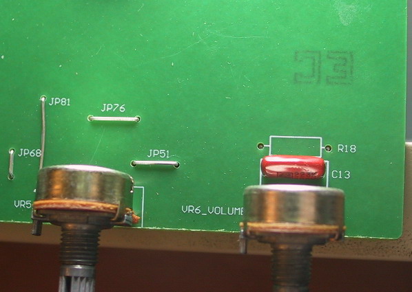
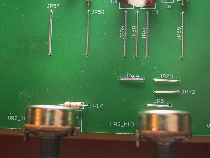
Hi,
I am trying to accomplish this mod on a Valve Special and markings do not match.
I am attaching 2 small pics to this message. Can you please confirm the connections I need to make on my PCB ?
Thanks !
Michel
| Attachment | Size |
|---|---|
| vr6.jpg | 65.95 KB |
| r17.jpg | 89.28 KB |
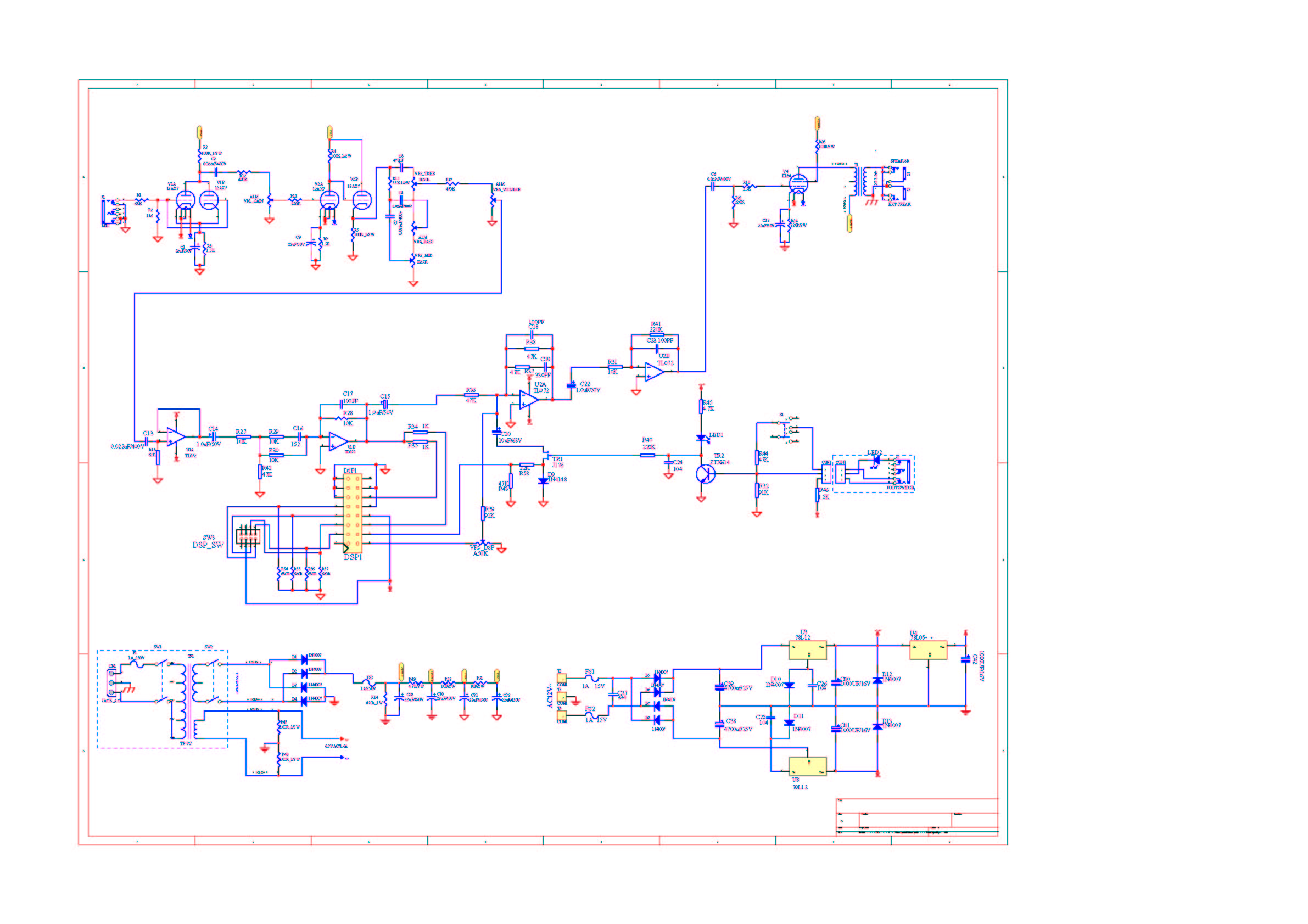
New Valve Special Revision
I think there is a new revision of the Valve Special. I asked Gibson for the schematic to my new VS (serial #07051409) and got a quick reply. They sent a low-res JPG of the schematic, which I'll attach. This version puts VR6 just after VR2, so the master volume control is before the solid-state section. I got half-way through doing the old-style SS bypass (connecting VR2 -> VR6) before I realised that it was already done and the bypass needs to be done at a different point ![]()
Did you end up doing the bypass on yours Michel?
| Attachment | Size |
|---|---|
| Schematic for Valve Special #07051409 | 314.98 KB |
Valve Standard conversion help request
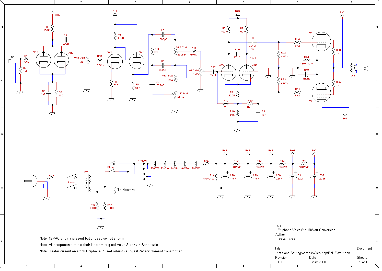
I could sure use some help on the conversion of an Epiphone Valve Standard to pseudo-18watt thing with elements of the 45watt putting in some appearances too. I have read through the several subject posts I've found here and a couple other places and put together a list of mods to make to a broken Valve Standard I picked up on the cheap. I have no idea what it used to sound like so part of my problem is I have no benchmark. But judging from the clips I've heard of real 18Watt and 45Watt amps, I shouldn't have these issues. Basically the amp sounds really good clean but stops being clean pretty quick. That's not a big issue 'cept the overdrive does not sound very good. It is very harsh, almost brittle sounding and the bass is flubbery - or maybe blatty is a better description with the harsh vibe on top of the flubberation (working on a new vocabulary - it too still has some rough edges ![]() ). Follows is a description of the mods and enclosed is a schematic that I made up of the amp as it is currently modified (I was going blind looking at that tiny little schematic Epiphone gives out).
). Follows is a description of the mods and enclosed is a schematic that I made up of the amp as it is currently modified (I was going blind looking at that tiny little schematic Epiphone gives out).
Ok, first off, I fully realize that I went way overboard on this putting way more work into it than it would have been to gut it and build a "real" 18watt. But it was also a learning experience for me and in that at least, it has been quite successful. I just wish the amp was a little bit more successful! Mods to the amp include the following (you'll recognize a lot of them from Zaphod's and BigJoe's lists):
- Disable and remove the solid state kruft. I don't mean just disconnect .. Perhaps I was bored or perhaps the SS stuff offended me in some fashion by sharing space in my tube amp so every solid state component, every jumper, every wire, etc that was not part of the ALL TUBE amp I wanted to be left was removed. In places where long traces went from tube stuff to solid state stuff that was no longer in use, I cut the traces near where the tube stuff was to eliminate any little "antennas" that could pick up noise or generate capacitance or whatever.
- The heaters were disconnected from the PCB board traces and soldered to the backs of the sockets (again cutting the old traces near the sockets).. Absolutely WORLDS of difference in the hum/buzz noise level. Amp is now quiet as a mouse 'cept right near the top of the MV dial.
- Grid stop resistors were often several inches and/or many snaking loops and turns of PCB traces away from the tube grid they were connecting to. These were replaced with shielded cable and the resistor soldered right to the back of the socket. This cured some oscillation issues I had been having.
- After reading the forums, a common theme that emerged was the shoddy quality of the components used, especially the polys. Since I had them around, I replaced ALL the caps .. both electrolytics and polys. Polys were replaces with a mixed bag of Mallorys and Wimas. Ceramics replaced with Silver Micas.
- My amp had two chassis ground points, one on the left side of the board, one on the right. Consolidating these got rid of yet another ground loop hum problem (Amp started out with more hum than guitar volume).
- C3 (tone stack) changed to .01uF from .022uF.
- R8 and R9 (cathode resistors) changed to 820R from 1K5 ohms.
- C1 (cathode bypass) changed to 1uF from 22uF.
- C9 (cathode bypass) was removed.
- R12 and R13 were changed to 220K from 1M. I did have R12 jumpered but put it back to 220K to try to calm the flubby bass issue. It dampened it along with the rest of the amp so I don't believe it is the problem and after the flubby bass issue is solved, plan to put it back to a jumper.
- C5 and C6 (power amp coupling caps) to .01uF from .022uF.
- R25 and R26 (screens) to 1K/3W from 100R/3W.
- Inserted two 9V/5W zeners between rectifier and fuse to bring voltage down a bit so EL84 plates do not exceed 350V (my voltages were not as high as BigJoe's).
- R21 (PI cathode resistor) changed to 470R from 1K2 ohms.
- C12 (power tube cathode bypass) changed to 1000uF/35V from 100uF.
- R17 changed to 220K from 470K (thinking I might change this back in case it is the PI generating the harsh overtones).
- Originally listed in the mods was changing R22/R23 to 330K from 220K but I had oscillation and *really* ugly tone issues doing this so this was undone and the resistors are back to 220K now. These *may* have been solved by some of the other oscillation changes but since this change added gain, I wasn't going to retry until the harsh blatt was controlled..
- R15 (tone stack) changed to 56K from 33K.
- C5 (tone stack) changed to 250pF from 500pF. Did this (and the 56K change) to brighten the tone a bit which was unaccountably dark before.
- I had changed the master volume pot to 500KA instead of 1MA but I'm now getting pretty much full volume within the first 1/8th to 1/4 turn. I think it was better with the 1MA pot but I haven't switched it back just yet.
- A 1M ohm resistor was put across VR4 (the 1MA bass pot) to make it effectively a 500KA pot.
- Output transformer changed out for a "real" 18Watt OT from GDS.
- Tubes changed to 3 Chinese 12AX7s and 2 JJ EL84s all from GDS.
For voltages, I have the following:
V1: pin1=121V pin2=0.6mV pin3=0.1V pin6=120V pin7=.5mV pin8=1V
V2: pin1=148V pin2=-2.3mV pin3=0.88V pin6=255V pin7=148V pin8=150V
V3: pin1=202V pin2=51V pin3=82.3V pin6=207V pin7=52V pin8=81.7V
V4: pin2=14mV pin3=13.2V pin7=349V pin8=343V
V5: pin2=8mV pin3=13.2V pin7=349V pin8=343V
Basically looking for ideas to try to reign this thing in and smooth it out. Like I said, I like overdrive. I like it a lot. But I have several high gain amps and don't want this to be one of them. Some decent smooth breakup would be good and then should I want more, I can push it with a pedal or something. It has a unique tone that I really like and I want to keep that.
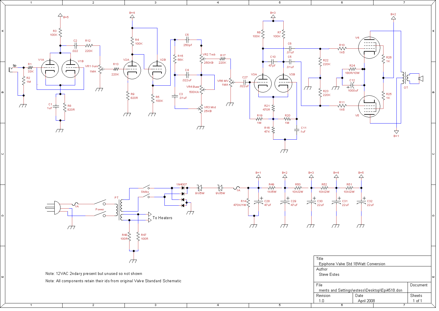
Enclosed is a schematic that I made of the amp as it exists. It is basically the Epiphone schematic sans all the SS crap and drawn to a scale that can be read when printed and it of course includes the mods above. I think I got everything right but if errors are spotted, please let me know. Done with TinyCAD hence the .png export. Note that the component numbers are unchanged from the Epiphone doc.
Thanks for any and all suggestions!
| Attachment | Size |
|---|---|
| Epi18Watt.png | 26.11 KB |
Epiphone Valve Standard
I am in the same process and after Big Joe's adventure and from what you also discribe;I think it would be better to gut this puppy and start from scratch...get a turret board and do the ptp wiring. This amp is a dark amp...the 1 meg resistors at R12
and R13 kill the tone completely. I liked the amp and bought it used..not because i wanted that kind of sound but I knew i could rework the electronics to get the desired sound i wanted; namely the 18 watt marshall. The Marshall lite schematic is very close to this one except for the extra 12ax7 preamp but the rest is the same. This amp I have built and it is remarkably close to the 18 watt marshall. I am sure that the epipi can be made to do the same. I agree with Big Joe.The OT has to be changes bar none. Also I disconnected the heater supply 6.3 volt leads from the transformer and put a 166N6 hammond in there instead. This puts out 4 amps. The heater filament leads on the original transformer are rated too low (1.62 amps) and if run at higher levels will burn them out. C2 is responsible for your bass..up it to .047uF for a little more bass....up to .1uF if you really want a lot of bass. BTW: i removed R12 and put R13 at 110K.Seemsw okay now but i will be throwing a scope on it tonight. More later.
Epiphone Valve Standard
Interestingly enough, I too have the Hammond filament xfmr in mine. One of the several things borked in the broken amp I got was fried filament windings in the PT. Didn't know the rating was that low on the stock heaters. After looking at the "quality" of the trace routing on the board (let's wind those filaments around every possible component to generate some bitchin noise!) I no longer wonder what they were thinking .. This thing was done on the cheap cheap cheap cheap with zero quality control at all. The price paid is good for the cab, chassis, a few odd components and *maybe* the PT. I've heard the speaker is no great shakes but I've never actually heard it. And yes, the GDS OT was a *major* upgrade ..
Wish there was a way to get this one to work as-is though.. I have an organ chassis I was going to do a full "normal" 18watt build in. Amp has plenty of bass in it. Just when I turn the MV pas about 10oclock, starts to pick up a real harsh top end like the PI is distorting badly or something. Same thing happened with the earlier sovtek tubes so I don't think it is tube related .. tiz something in the amp itself.
Epiphone Valve Standard
Guess thats why they have been discontinued:)I noticed epiphone doesn't list the valve standard or the special on thier site anymore.The So-Cal 50H and the blues 30 seemed to hang on though.I own the So-Cal as well and i have absolutely no issues with that head..it honks. I didn't bother buying the Cab that goes with it...just used a Marshall 1960S on it and it rocks.
On the other hand..i hate draggin around over 100lbs. of gear just to jam.The Standard
seems to be luggable and at most worth friggin with.
Here's something I have done this afternoon. I printed off your schematic, the one mentioned above (matchless lightening)which by the way is almost a direct copy of the standard cept for several parts, got a copy of the 18 wat light (sans tremolo) and did some deep comparison..here goes:
Following your schematic :change R1 to 68k
make R3 220k, C2 is .0012uf, C1 is 50uf ,jump R12, put 180pf on VR1 from wiper to where C2 attaches, jump R13 , Put C9 Back as 50uf.
change R5 to 56k.....now comes the tone stack...2 choices here...1.keep what you have or
download duncans amp tools and play with the values until you are satisfied with the tone scheme you are looking for. I chose to go with the Marshall standard..which is what the epipi has now.may change it later.
Make R17 570k..keep the PI from kicking the crap out of the finals.
make C27 .01uf
Now for the fun part: change R21 to 820ohms, R19,20 to 470k.
Last but least...do this with the finals:
change R22,23 to 470k
make R10,11 to 8.2k
make R24 150ohm at 5 watt and C12 100uf
lastly ditch that crappy epiphone speaker and throw in a vintage 30 or greenback USA brand and your good to go!!!!
the above gribnick is a culmination of the matchless front end up to the PI and the Marshall tone stack (original) and output as seen in the Marshall lite schematic.
BigJoe and you were absolutely right on though..get rid of the dual grds and hack off those long frigging antennas (traces) put all resistors on the tubes..grid ...etc.
I was going to put a couple of 1/4" jacks in the back of her and use these as inserts
so i could use the reverb portion of the DSP. Haven't decided yet.
Anyways keep me post on what you come up with....
Re: Epiphone Valve Standard
The Valve Standard is closer IMO to an 18W TMB amp, such as Richies' TMB on 18watt.com than an 18W Lite IIb. Basically you get an 18W TMB with a parallel triode first stage and no Normal channel. In any case, the mods you suggest are good, as they bring the Valve Standard closer to an 18W. However, I wouldn't necessarily jump to using a 100uF cathode cap on the EL84s with the 150 ohm resistor, as the 1000uF/180 ohms will deliver smoother distortion and tighter bass. I think it might be good to experiment with those different values, since tastes vary a lot. Maybe also try increasing the drive on the el84s, 18W style, by increasing R22 and R23 to 330k or 470k, depending on how much you want to push the power tubes.
To control the low end C2 can be reduced to 0.01uF. Some people also like to use a 2.7k value for R9, with a 0.68uF across it when more boost is required, which can also really help reduce any woofiness. For R1 I would actually recommend using 10k rather than 68k, as this will be less likely to pick up buzz, while allowing more sparkle from the guitar to come through.
Just a few ideas....
Epiphone Valve Standard con't :)
Dually noted and much appreciated Zaphod! Alot of changes are of personal taste...
experimentation is always and highly recommended. The biggy with this amp is the lousy PT heater taps (low amperage rating) and the OT....the speaker i won't even comment on:)
The whole amp is very salvagable though and as you said;tweeking the values will surely
prove worthwhile in the long run. I picked up this amp as an experiment. It is solidly built and heavy enough to produce a good hernia.However, I knew once I got it home I would have to do some experimenting:)
Luckily there are guys like you and and forums like this that provide superior intel on
such modz...I am by no means an expert..the amps i deal with are of the RF variety and run a cool 50,000 watts...these are the ones i was trained on.
So i am all ears when it comes to perfecting that "perfect amp".
Thanks Zaphod for your input...I will surely be trying them as this weekend I have set aside to experiment on the beast.
Bypassing DSP.
I had someone bring me their standard to bypass the DSP. To do it right is a good couple of hours(PCB removal,job and re-assemble) and a new MVpot as noted above. It would be silly to just do that mod once the chasis is already out. I decided not to take the job. If I owned the amp and wasn't billing myself ![]() I would do all sorts of stuff. I told the guy it's not worth it unless he did the work himself. How much time do feel you've invested bigjoe?
I would do all sorts of stuff. I told the guy it's not worth it unless he did the work himself. How much time do feel you've invested bigjoe?
Remember to keep one hand in your pocket!
Epiphone Valve Standard con't
I bet Big Joe has spent countless hours perfecting the beast to the sound he desired.
There are so many things you can change in this amp to get whatever sound you want..I guess the real issue is time. Is it worth it??..for the educational aspect I believe it is.
Amp guys and tube guys love a challenge and I have no doubt that Big Joe is committed to finding the Holy Grail of sound within this beast...I am also committed as well but might be committed institutionally afterwards from all the hours I have been noodling around looking for that "perfect"sound.
I am pretty close now...when i finish it up i will post the PDF of what i did with a detailed discription. Thanks to all members for their valuble contributions especially Big Joe and Zaphod_Phil for all there suggestions..it truly makes a project like this
alot more fun when such knowledgable people are there to help!!
Epiphone Valve Standard con't
I have made progress. Latest schematic is attached. I had a misunderstanding on what the voltages should be for the EL84. I thought they were supposed to be under 350V but looking at a JJ tube data sheet last nite said under 300V so my 348V was way too high. I added in the other 3 zeners I hadn't added (total now 5 as was originally recommended) and that brought the plate voltages down to the 320V range which is inline with the voltages bigjoe posted near the top of this topic.
Still had over-fuzz condition on preamp (and no headroom). My Schecter C1 Classic (JB/Jazz Seymour pups) got dirty on the bridge pickup with mv and pre just cracked enough to make noise. So I cleaned up the preamp some more, which got me a decent clean yet still got dirty on the high end. Has sufficient treble too which is cool. I also had to give the PI some more headroom going back to many of the original epi values here. It still gets really loose and loses all definition and coherency when you dime it. Read as zero articulation. Power chords just sound like loud blatts (could be blocking distortion but from where??!?!). But it sounds quite nice so long as gain and mv don't go past about 3/4s .. is this typical of 18 watts? I've never played one so have no basis for reference. It also isn't all that loud anymore. I would have liked more volume out of it but it seems hitting the power tubes with that much boost drives 'em nuts so to speak..
Biggest annoyance right now is with all those zeners in there I've picked up a really annoying constant buzz. Very harsh. I've heard zeners are excellent buzzsaw noise radiators so I'm assuming that is what I have. They are located on the board but up in the upper right hand corner where a bunch of solid state stuff used to be. They aren't really near any thing except they are about 1.5 inches away from the el84s (which are on the other side of the board. Not sure if they are able to radiate that far or if the el84s could somehow be better shielded or if I just need to get a real power supply and quit messing around with this epiphone crap (which would also get rid of the heater supply xfrmr I'm using right now too). The PT275 from musicalpowersupplies.com looks like it could be up to the job. And the price is certainly right!
| Attachment | Size |
|---|---|
| Epi18Watt1.3.png Epiphone Valve Standard 18Watt Conversion | 26.64 KB |
Post new comment
This site is run by unpaid, volunteer moderators, some of which have commercial interests in the guitar amplification business. They will all attempt to the best of their abilities to not interfere with commercial discussions. All messages on this forum express the views of the author and do not necessarily reflect the opinions of the site and (or) its administrators. This site will not be held responsible for the content of any messages posted on this forum. The operation of this site is supported financially by its members.
Joined: 2003-03-19